
1. General
This type of valve is designed to be an open-and-shut installation to keep the proper operation used in industrial pipeline system.
2. Product Description
2.1 Technical requirement
2.1.1 Design and Manufacture Standard:API 600、API 602
2.1.2 Connection Dimension Standard:ASME B16.5 etc
2.1.3 Face to Face Dimension Standard:ASME B16.10
2.1.4 Inspection and Test:API 598 etc
2.1.5 Size:DN10~1200,Pressure:1.0~42MPa
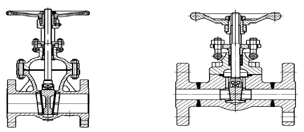
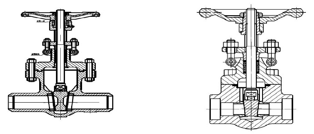
2.2 This valve is equipped with flange connection, BW connection manual operated casting gate valves. The stem moves in the vertical direction. Gate disc shuts the pipeline during the clockwise circling of hand wheel. Gate disc opens the pipeline during counterclockwise circling of hand wheel.
2.3 Please reference the structure of the following drawing
2.4 Main Components and Material
| NAME | MATERIAL |
| Body /Bonnet | WCB、LCB、WC6、WC9、CF3、CF3M CF8、CF8M |
| Gate | WCB、LCB、WC6、WC9、CF3、CF3M CF8、CF8M |
| Seat | A105、 LF2、F11、F22、F304(304L)、F316(316L) |
| Stem | F304(304L)、F316(316L)、2Cr13,1Cr13 |
| Packing | Braided graphite & Flexible graphite & PTFE etc |
| Bolt/Nut | 35/25、35CrMoA/45 |
| Gasket | 304(316)+Graphite /304(316)+Gasket |
| SeatRing/Disc/Sealing |
13Cr、18Cr-8Ni、18Cr-8Ni-Mo、PP、PTFE、STL etc |
3. Storage & Maintenance & Installation & Operation
3.1 Storage & Maintenance
3.1.1 Valves should be stored in the indoor condition. The cavity ends should be covered by plug.
3.1.2 Periodic inspection and clearance is required for long time stored valves, especially for sealing surface cleaning. No damage is allowed. Oil coating is requested to avoid rust for machining surface.
3.1.3 Concerning the valve storage more than 18 months, tests are required before valve installation and record the result.
3.1.4 Valves should be periodically inspected and maintained after installation. Main points are as the below:
1)Sealing surface
2)Stem and Stem nut
3)Packing
4)Internal surface cleaning of Body and Bonnet.
3.2 Installation
3.2.1 Recheck the valve markings (Type, DN, Rating, Material) which complies with markings requested by pipeline system.
3.2.2 Complete cleaning of cavity and sealing surface is requested before valve installation.
3.2.3 Ensure the bolts are tight before installation.
3.2.4 Ensure the packing is tight before installation. However, it should not disturb stem movement.
3.2.5 Valve location should be convenient for inspection and operation. Horizontal to pipeline is preferred. Keep hand wheel up and stem vertical.
3.2.6 For shut-off valve, it is not suitable to be installed in high pressure working condition. Stem should be avoided to be damaged.
3.2.7 For Socket welding valve, attentions are requested during valve connection as the following:
1)Welder should be certified.
2)Welding process parameter must be in conformance to relative welding material quality certificate.
3)Filler material of welding line, the chemical and mechanical performance together with anti-corrosion should be similar to body parent material.
3.2.8 Valve installation should avoid high pressure from attachments or pipes.
3.2.9 After installation, valves should be open during pipeline pressure test.
3.2.10 Support Point:if the pipe is strong enough to support valve weight and operation torque, the support point is not requested. Otherwise it is needed.
3.2.11 Lifting:Hand wheel lifting is not allowed for valves.
3.3 Operation and Usage
3.3.1 Gate valves should be completely open or closed during usage to avoid seat sealing ring and disc surface caused by high speed medium. They can’t be sued for flow regulation.
3.3.2 Hand wheel should be used to replace other instruments to open or close valves
3.3.3 During the allowed service temperature, instantaneous pressure should be lower than rated pressure according to ASME B16.34
3.3.4 No damage or strike is allowed during valve transportation, installation and operation.
3.3.5 Measure instrument to check the unstable flow is requested to control and get rid of the decomposition factor to avoid valve damage and leakage.
3.3.6 Cold condensation will influence valve performance, and measure instruments should be used to reduce flow temperature or replace the valve.
3.3.7 For self-inflammable fluid, use appropriate measuring instruments to guarantee ambient and working pressure do not exceed its auto-ignition point (especially notice sunshine or external fire).
3.3.8 In case of dangerous fluid, such as explosive, inflammable, toxic, oxidation products, it is prohibited to replace packing under pressure. Anyhow, in emergency case, it is not recommended to replace packing under pressure (although the valve has such a function).
3.3.9 Make sure the fluid is not dirty, which affects valve performance, not including hard solids, otherwise appropriate measuring instruments should be used to remove the dirt and hard solids, or replace it with other type of valve.
3.3.10 Applicable working temperature
| Material | Temperature |
Material |
Temperature |
| WCB | -29~425℃ |
WC6 |
-29~538℃ |
| LCB | -46~343℃ | WC9 | --29~570℃ |
| CF3(CF3M) | -196~454℃ | CF8(CF8M) | -196~454℃ |
3.3.11 Make sure material of valve body is suitable for use in corrosion resistant and rust preventing fluid environment.
3.3.12 During service period, check for sealing performance as per the table below:
| Inspection point | Leak |
| Connection between valve body and valve bonnet |
Zero |
| Packing seal | Zero |
| Valve body seat | As per technical specification |
3.3.13 Regularly check for the wear of seating fare, packing aging and damage.
3.3.14 After repair, re-assemble and adjust the valve, then test tightness performance and make records.
4. Possible problems, causes and remedial measures
|
Problem description |
Possible cause |
Remedial measures |
|
Leak at packing |
Insufficiently compressed packing |
Re-tighten packing nut |
|
Inadequate quantity of packing |
Add more packing |
|
|
Damaged packing due to long-time service or improper protection |
Replace packing |
|
|
Leak on valve seating face |
Dirty seating face |
Remove dirt |
|
Worn seating face |
Repair it or replace seat ring or valve plate |
|
|
Damaged seating face due to hard solids |
Remove hard solids in the fluid, replace seat ring or valve plate, or replace with other type of valve |
|
|
Leak at connection between valve body and valve bonnet |
Bolts are not properly fastened |
Uniformly fasten bolts |
|
Damaged bonnet sealing face of valve body and valve flange |
Repair it |
|
|
Damaged or broken gasket |
Replace gasket |
|
|
Difficult rotation of hand wheel or valve plate can’t be opened or closed. |
Too tightly fastened packing |
Appropriately loosen packing nut |
|
Deformation or bending of sealing gland |
Adjust sealing gland |
|
|
Damaged valve stem nut |
Correct thread and remove the dirty |
|
|
Worn or broken valve stem nut thread |
Replace valve stem nut |
|
|
Bent valve stem |
Replace valve stem |
|
|
Dirty guide surface of valve plate or valve body |
Remove dirt on guide surface |
Note: Service person should have relevant knowledge and experience with valves Water sealing gate valve
The bonnet packing is water sealing structure, it will be separated from the air while the water pressure reaches to 0.6~1.0MP to guarantee good air sealing performance.
5.Warranty:
After the valve is put into use, the warranty period of valve is 12 months, but does not exceed 18 months after delivery date. During warranty period, the manufacturer will provide repair service or spare parts free of charge for the damage due to material, workmanship or damage provided that operation is correct.
Post time: Nov-10-2020