
1. Scope
This manual includes electric operated, pneumatic operated, hydraulic operated and oil-gas operated flanged connection three-piece forged trunnion ball valves and fully welded ball valves with nominal size NPS 8~36 & Class 300~2500.
2. Product Description
2.1 Technical requirements
2.1.1 Design and Manufacture standard : API 6D、ASME B16.34
2.1.2 End to end connection standard: ASME B16.5
2.1.3 Face to face dimension standard: ASME B16.10
2.1.4 The pressure-temperature grade standard: ASME B16.34
2.1.5 Inspection and test (including hydraulic test): API 6D
2.1.6 Fire resistance test: API 607
2.1.7 Sulfur resistance processing and material inspection (applicable to sour service): NACE MR0175/ISO 15156
2.1.8 Fugitive emission test (applicable to sour service): as per BS EN ISO 15848-2 Class B.
2.2 The structure of ball valve
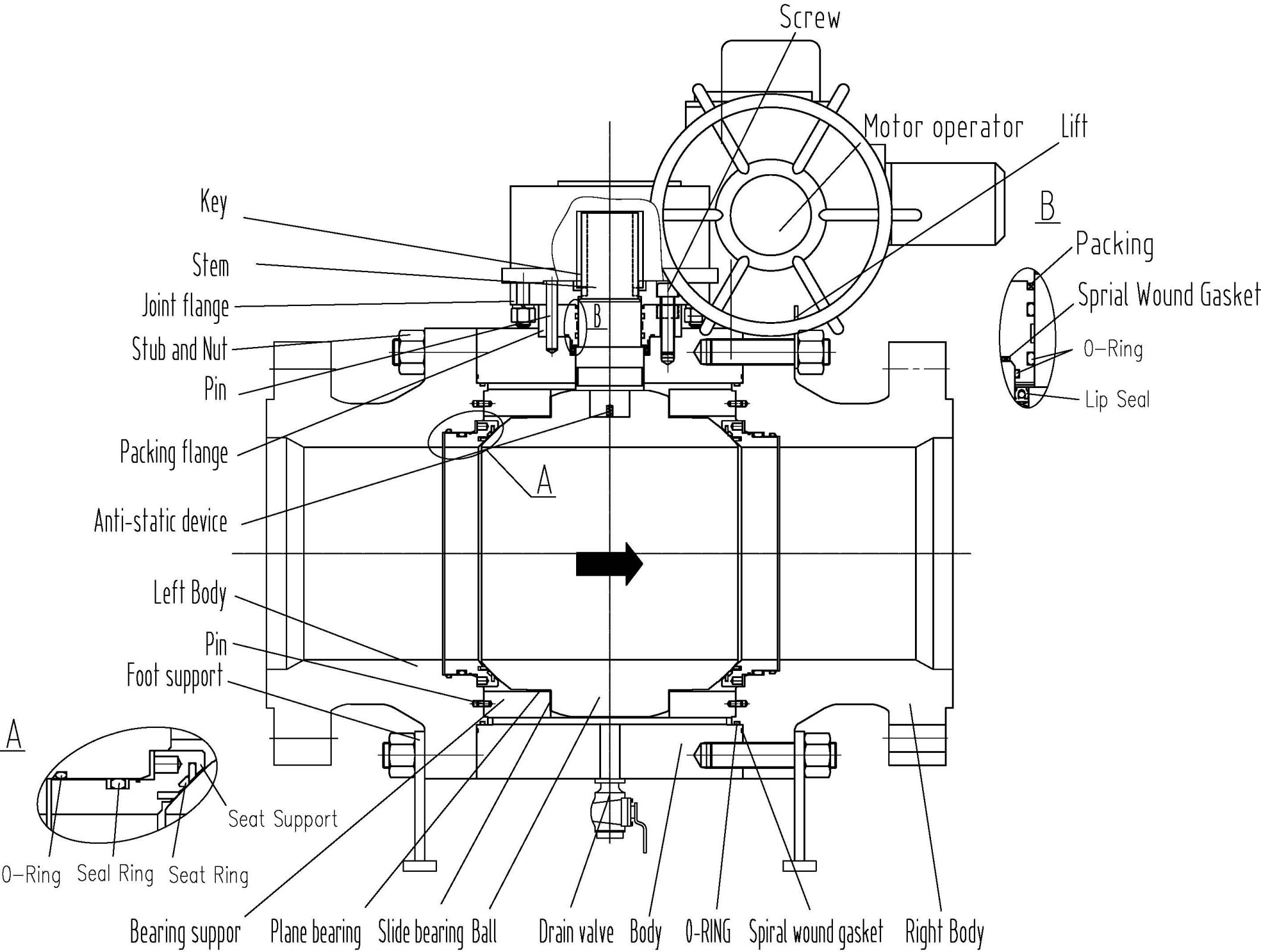
Figure1 Three pieces forged trunnion ball valves with electric actuated
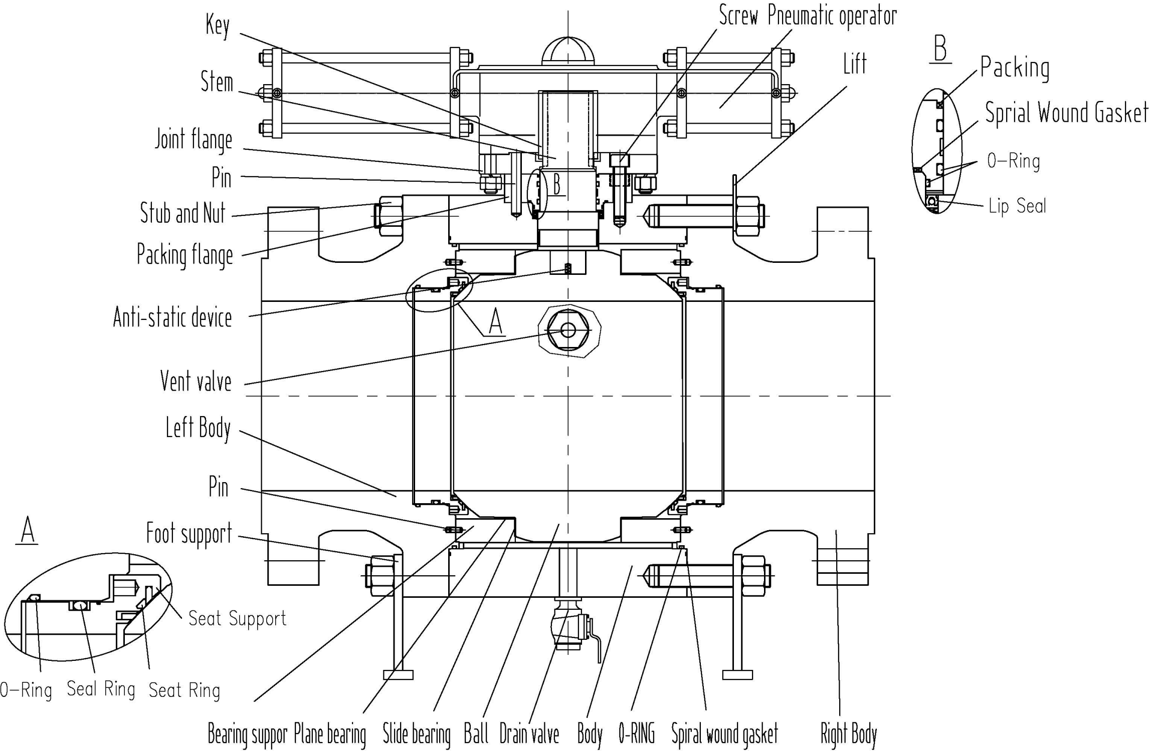
Figure2 Three pieces forged trunnion ball valves with pneumatic actuated
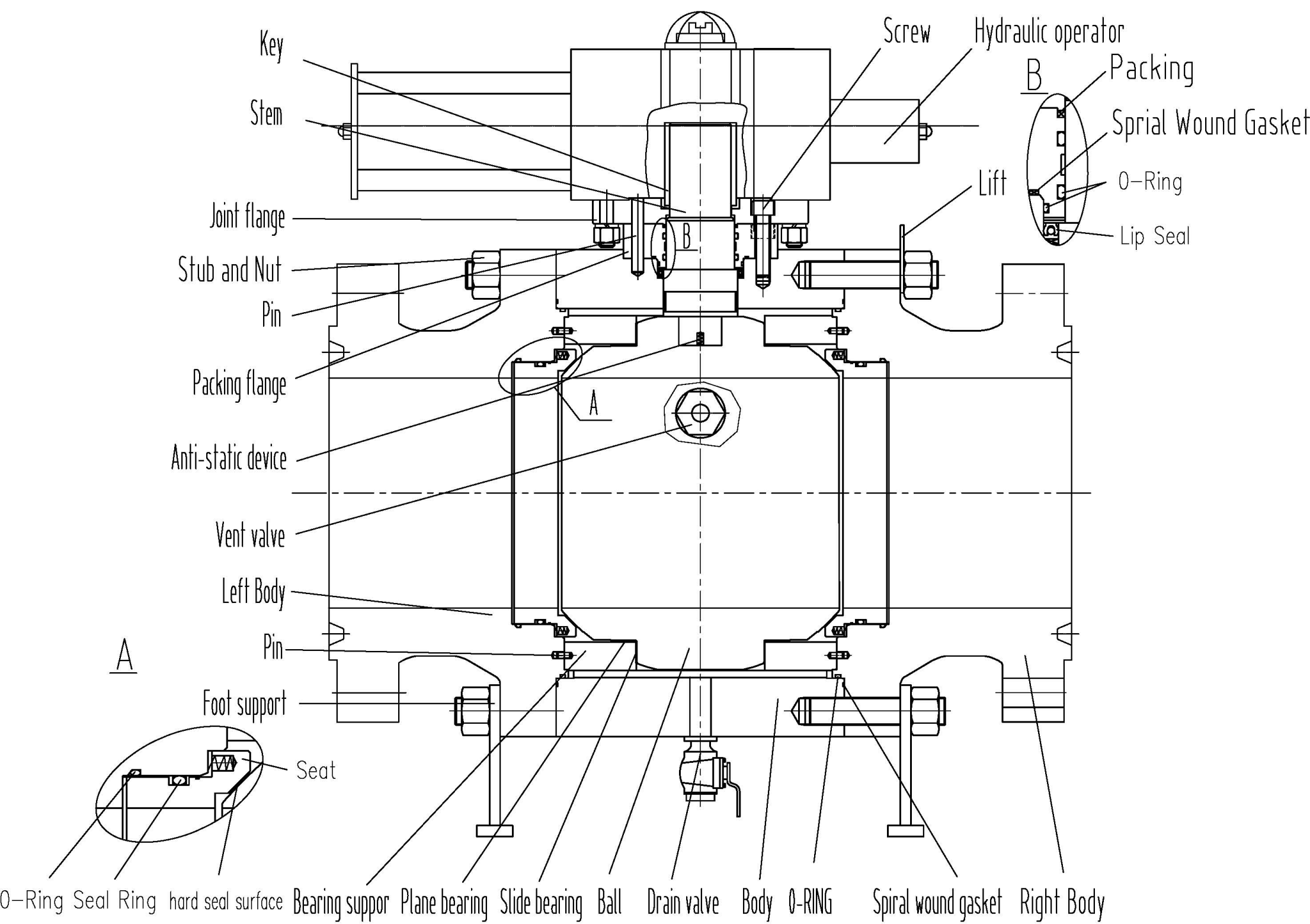
Figure3 Three pieces forged trunnion ball valves with hydraulic actuated
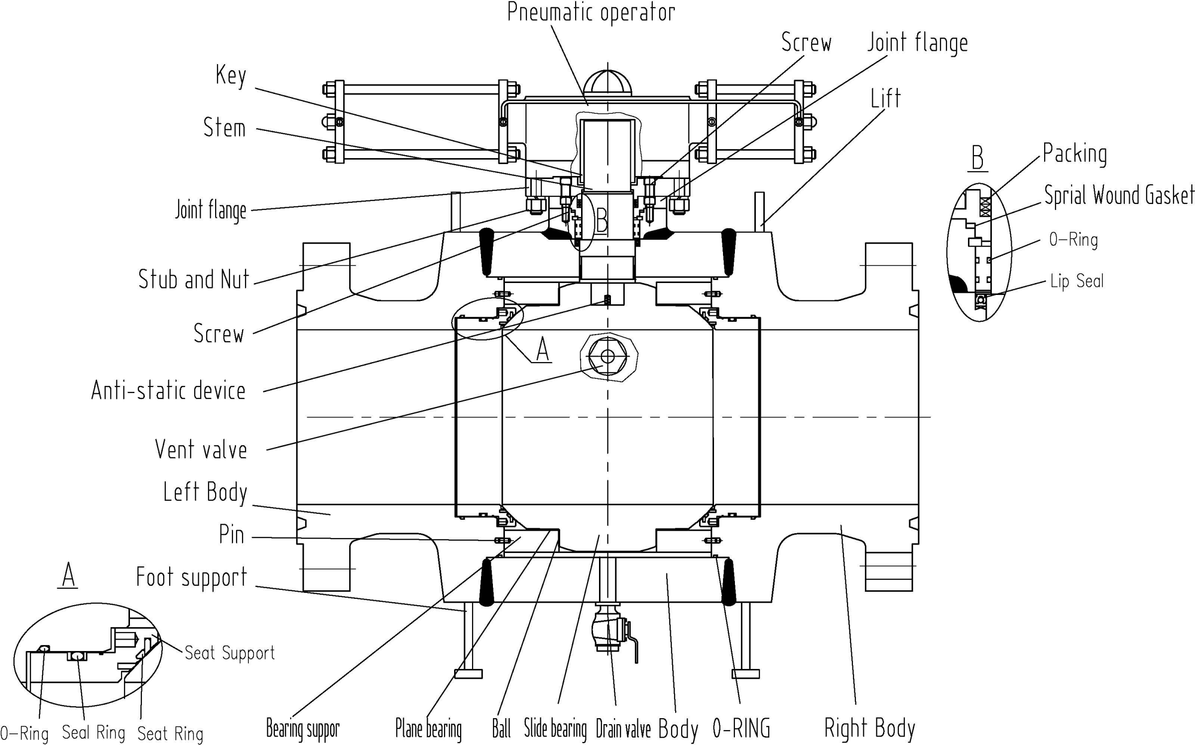
Figure4 Fully welded ball valves with pneumatic actuated
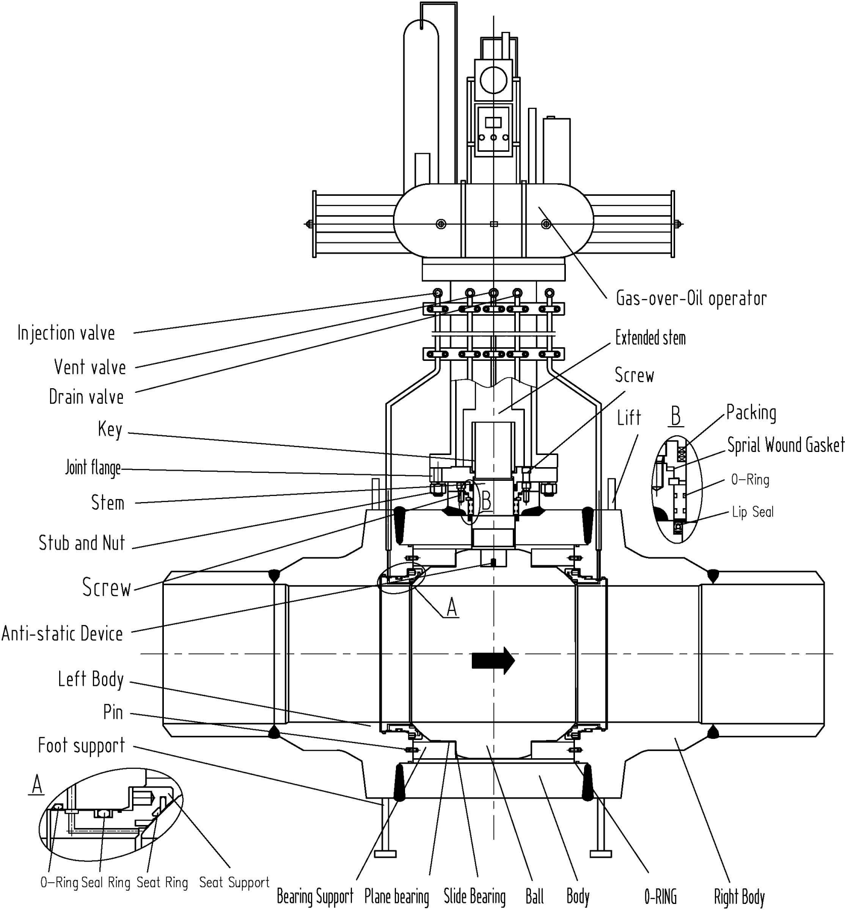
Figure5 Buried fully welded ball valves with oil-gas actuated
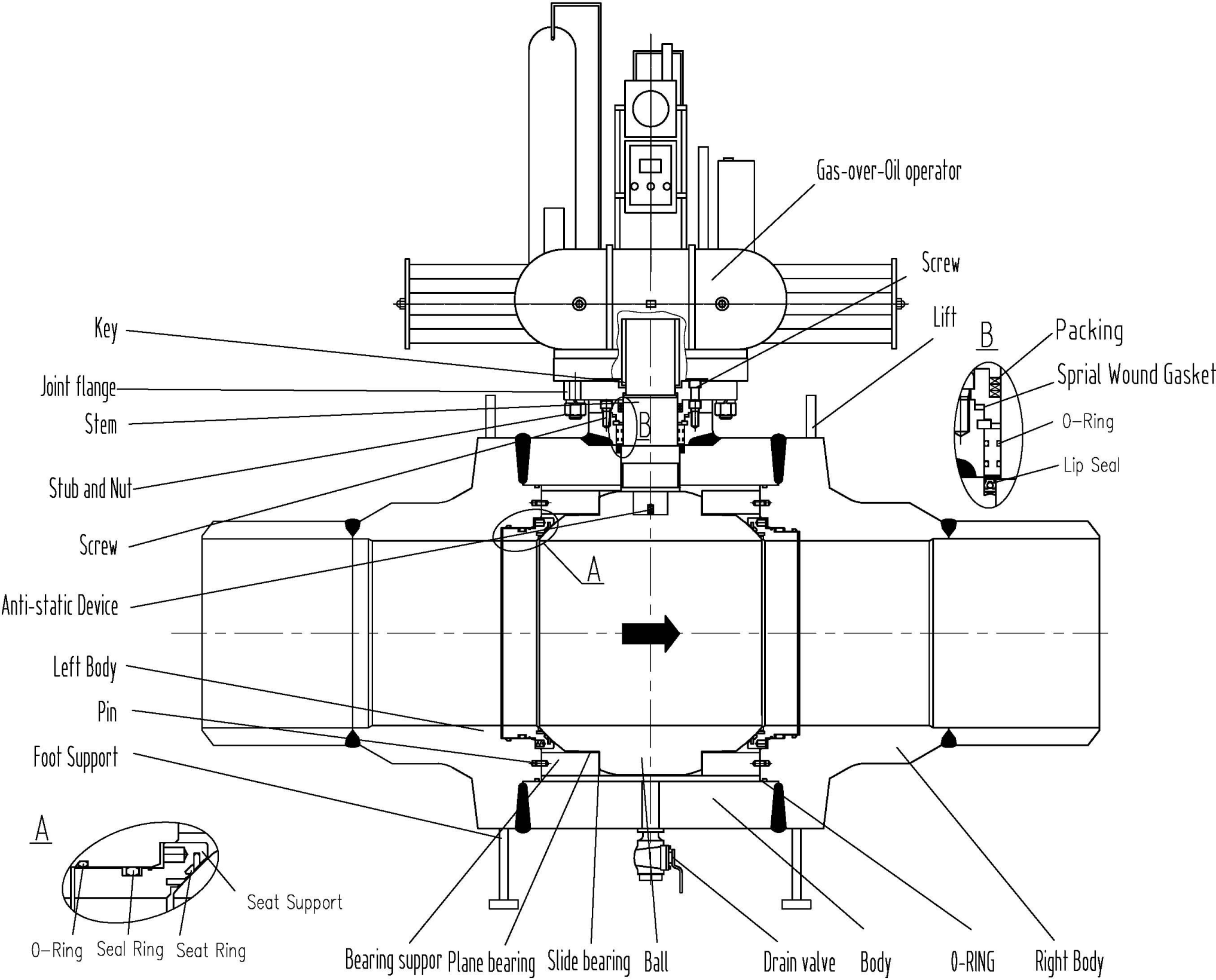
Figure6 Fully welded ball valves with oil-gas actuated
3. Installation
3.1 Pre-installation preparation
(1) Both end pipeline of valve has been ready. Front and rear of pipeline should be coaxial, two flange sealing surface should be parallel.
(2) Clean pipelines, the greasy dirt, welding slag, and all other impurities should be removed.
(3) Check the marking of ball valve to identify the ball valves in good condition. The valve shall be fully opened and fully closed to confirm that it is working properly.
(4) Remove the protective accessories in the connection of the both end of valve.
(5) Check the valve opening and clean it thoroughly. Foreign matter between the valve seat/seat ring and the ball, even if only a granule may damage the valve seat sealing face.
(6)Before installation, carefully check the nameplate to ensure valve type, size, seat material and the pressure-temperature grade are suitable to the condition of pipeline.
(7)Before installation, check all the bolts and nuts in the connection of valve to guarantee it is tightened.
(8)Careful movement in transportation, throwing or dropping is not allowed.
3.2 Installation
(1) The valve installed on the pipeline. For media flow requirements of the valve, confirm the upstream and downstream accordance with the direction of valve to be installed.
(2) Between valve flange and pipeline flange should be installed the gaskets according to the requirements of pipeline design.
(3) Flange bolts should be symmetrical, successive, evenly tighten
(4) The butt welded connection valves shall at least meet the following requirements when they are welded for installation in pipeline system on site:
a. Welding should be carried out by the welder who possesses welder’s qualification certificate approved by the State Boiler and Pressure Vessel Authority; or the welder who has obtained welder’s qualification certificate specified in ASME Vol. Ⅸ.
b. Welding process parameters must be selected as specified in the quality assurance manual of welding material
c. The chemical composition, mechanical performance and corrosion resistance of the filler metal of welding seam should be compatible with base metal
(5) When lifting with the lug or the valve neck and the sling chain fastening at hand wheel, gear box or other actuators are not allowed .Also, the connection end of valves should pay attention to protect from being damaged.
(6)Body of the welded ball valve is from the butt end weld 3 “at any point on the outside of the heating temperature shall not exceed 200 ℃. Before welding, the measures should be taken to prevent impurities such as welding slag in the process of falling into the body channel or the seat sealing. The pipeline which sent the sensitive corrosion medium should be taken the weld hardness measurement. The hardness of welding seam and base material is not more than HRC22.
(7)When installing valves and actuators, the axis of actuator worm should be perpendicular to the axis of the pipeline
3.3 Inspection after installation
(1) The opening and closing 3~5 times for the ball valves and actuators should be not blocked and it confirms that the valves can work normally.
(2) The connection face of flange between pipeline and ball valve should be checked the sealing performance according to the requirements of pipeline design.
(3)After installation, the pressure test of system or pipeline, the valve must be in the fully open position.
4 .Operation, storage and maintenance
4.1 Ball valve is 90 °opening and closing type, ball valve is only used for switching and does not used for adjusting! It is not allowed that the valve used in the above temperature and pressure boundary and frequent alternating pressure, temperature and working condition of use. The pressure-temperature grade shall be in accordance with ASME B16.34 Standard. The bolts should be tightened again in case of leakage at high temperature. Don’t allow to impact loading and the phenomenon for high stress does not allow appearing at low temperature. The manufacturers are irresponsible if an accident occurs because of the violation of the rules.
4.2 User should fill lubricating oil (grease) regularly if there are any grease valves which belong to lube type. Time should be set by user according to the frequency of valve opens, usually once every three months; if there are any grease valves which belong to seal type, sealing grease or soft packing should be filled timely if users find leakage, and it makes sure that there is no leakage. User always maintenance the equipment in good condition! If there are some quality problems during the warranty period (according to the contract), the manufacturer should go to the scene immediately and solve the problem. If more than warranty period (according to the contract), once the user needs us to solve the problem, we will go to the scene immediately and solve the problem.
4.3 The clockwise rotation of manual operation valves shall be closed and the counterclockwise rotation of manual operation valves shall be open. When the other ways, the control box button and instructions should be consistent with the switch of valves. And avoid the wrong operation will avoid to occur. Manufacturers are irresponsible due to operational errors.
4.4 The valves should be regular maintenance after the valves are used. The sealing face and abrasion should be often checked, such as if packing is aging or failure; if body occur the corrosion. If the above situation occurs, it is timely to repair or replace.
4.5 If the medium is water or oil, it is suggested that valves should be checked and maintained every three months. And if the medium is corrosive, it is suggested that all the valves or part of valves should be checked and maintained every month.
4.6 Ball valve usually does not have thermal insulation structure. When the medium is high temperature or low temperature, the surface of valve is not allowed to touch to prevent from burn or frostbite.
4.7 The surface of valves and stem and other parts cover easily dust, oil and medium infectant. And the valve should be abrasion and corrosion easily; even it is caused by friction heat generating the risk of explosive gas. So the valve should often clean in order to ensure the good working.
4.8 When valve repair and maintenance, the same as the original size and material o-rings, gaskets, bolts and nuts should be used. O-rings and gaskets of valves can be used as a repair and maintenance spare parts in purchase order.
4.9 It is prohibited to remove the connection plate to replace the bolts, nuts and o-rings when the valve is in the pressure condition. After the screws, bolts, nuts or o-rings, the valves can reuse after sealing test.
4.10 In general, the internal parts of valves should be preferred to repair and replace, it is best to use parts of manufacturers for replacement.
4.11 The valves should be assembled and adjusted after the valves are repaired. And they should be tested after they are assembled.
4.12 It is not recommended that user keep repairing the pressure valve. If the pressure maintenance parts have been used for a long time, and the possible accident will occur, an even it affects the user security. Users should replace the new valve timely.
4.13 The welding place for welding valves on the pipeline is prohibited to repair.
4.14 The valves on the pipeline are not permitted to tap; it is just for walking and as any heavy objects on it.
4.15 The ends should be covered with the shield in dry and ventilated room, to ensure pureness of valve cavity.
4.16 Large valves should be propped up and can not contact with the ground when they store in outdoor Also, the waterproof moisture-proof should be noticed.
4.17 When valve for the long-term storage is reused, the packing should be checked whether it is invalid and fill lubricant oil into the rotating parts.
4.18 The working conditions of valve must keep clean, because it can extend its service life.
4.19 The valve for long-term storage should be check regularly and remove dirt. The sealing surface should pay attention to be clean to prevent from damage.
4.20 The original packaging is stored; the surface of valves, stem shaft and flange the sealing surface of flange should pay attention to protect.
4.21 The cavity of valves is not allowed to drain when the opening and closing does not reach the designated position.
5. Possible problems, causes and remedial measures (see form 1)
Form 1 Possible problems, causes and remedial measures
|
Problem description |
Possible cause |
Remedial measures |
| Leakage between the sealing surface | 1. Dirty sealing surface2. The sealing surface damaged | 1. Remove dirt2. Re-repair or replace it |
| Leakage at stem packing | 1. Packing pressing force is not enough2. Damaged packing due to long-time service3.O-ring for stuffing box is failure | 1. Tighten the screws evenly to compact the packing2. Replace packing |
| Leak at connection between valve body and left -right body | 1.Connection bolts fastening uneven2. Damaged flange face3. Damaged gaskets | 1. Evenly tightened2. Repair it3. Replace gaskets |
| Leakage the grease valve | The debris are inside grease valves | Clean with little cleaning fluid |
| Damaged the grease valve | Install and replace auxiliary greasing after the pipeline reduce the pressure | |
| Leakage the drain valve | Damaged the sealing of the drain valve | The sealing of drain valves should be checked and cleaned or replaced directly. If it is damaged seriously, the drain valves should be replaced directly. |
| Gear box/actuator | Gear box/actuator failures | Adjust, repair or replace gear box and actuator according to the gear box and actuator specifications |
| Driving not flexible or ball don’t open or close. | 1. The stuffing box and the connection device is skewed2. The stem and its parts have damaged or dirt.3. Many times for open and close and dirt at the surface of ball | 1. Adjust packing, packing box or the connection device.2.Open, repair and remove sewage4.Open ,clean and remove sewage |
Note: Service person should have relevant knowledge and experience with valves
Post time: Nov-10-2020